Showing posts with label Database. Show all posts

Saturday, June 6, 2015

Normalization


-  It deals with the database design problem

- Normalization process concerns with the transformation of the conceptual schema (logical data structure) into computer representable form.

- It is a process of restricting data into tables; in order to ensure efficient & reliable storage & smooth retrieval of data.

Database Schema

A database schema of a database system is its structure described in a formal language supported by DBMS


Formal Language 
  •  Finite set of strings, symbols or tokens that defines a DBMS
Thus, schemas are the set of formula/rules that specify the integrity constraints imposed on Database.


Need Of Normalization

As time passes, there will be need for most databases to grow by adding new attributes and new relations. The data will be used in new ways. Tuples will be added & deleted.

Information stored will go updation also. New associations may also be added. In these suitations, the performance of the DB is dependent upon its design. A bad database design may lead to certain undesirable things like:

- Repetition of Information
- Inability to report certain information
- Loss of Info.

All this may lead to rewriting of application. Thus Normalization, helps to attain database design & ensures the efficiency of database

Advantages of Normalization

- Reduces data redundancies
- It helps in eliminating data anomalies
- It produces controlled redundancies to link tables


Database Integrity

    DB contained, data employed by many users. It is important that the data item & associated relation b/w them not to be destroyed. 

     The DBMS designed, includes some certain types of checks that ensures that the data entered in the table conforms to certain rules which in terms does not violates the original data structure of DB.

      Eg. No. of days an emp. Worked in a month can’t exceed the no. of days in a month.
  
First Normal Form (1NF)

A relation is in 1NF if and only if all underlying domains of each relation contain  atomic(indivisible) values, and the value of each attribute contains only a single value from that domain.

A row of data cannot contain repeating group of data i.e each column must have a unique value. Each row of data must have a unique identifier i.e Primary key. For example consider a table which is not in First normal form


  • All Key Attributes defined
  • No repeating groups in table
  • All attributes dependent on Primary Key

Second Normal Form (2NF)


Functional Dependence 
      In a given table, an attribute Y is said to have a functional depends on a set of attributes  X(X->Y)
      If and only if(iif)

      Each X value is associated with precisely one Y value

   
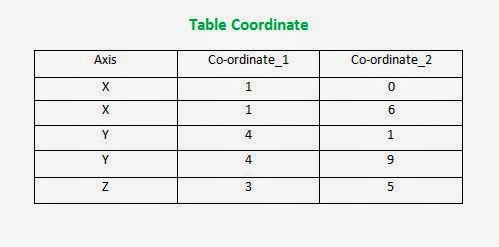
Here, is a Realation(Table),  R (Coordinate)     
R{Axis, Co-ordinate_1, Co-ordinate_2}  are its attributes

(Co-ordinate_1)  ------> (Axis) => Co-ordinate_1 is functionally dependent on Axis
(Co-ordinate_2)  ------> (Axis) => Co-ordinate_2 is functionally dependent on Axis

(Co-ordinate_1)  non-dependent on (Co-ordinate_2) 

Partial Dependency  refers to the dependency of a non-key (not assigned key constraints) on the portion of the composite-primary-key and not the whole primary key.


 Hence,  

A relation R is in 2NF if and only if (iif) it is in 1NF and every non-key attribute is fully dependent on the primary key.


Saturday, April 20, 2013

Database Keys


Keys

A key is a single or combination of multiple fields. Its purpose is to access or retrieve data rows from the table account to the requirement.

  • The keys are defined in the table to access / sequence the stored data quickly & smoothly.
  • They are used to provides link b/w tables.


Purpose of Keys

  • To ensure that each record in a table is precisely identified 
  • To help in establishing & enforcing various types of integrity constraints
  • To establish table relationship

Types of Keys
  • Super Key
  • Candidate Key
  • Primary Key
  • Secondary/Alternate Key
  • Composite/Concatenate/Compound Key
  • Foreign Key


Super Key

It is a set of attributes of a relation variable for which it holds that in all relations assigned to that variable there are no two distinct tuples that have the same value for attributes in this set. A relation can have multiple superkeys.
  • Super key is a key represents a column or set of columns that uniquely identifies a record.
  • Any unique key with some non-unique key combination is called a superkey of that relationship.

Primary Key

  • The attribute or combination of attribute that uniquely identifies a row or a record.
  • It is the min. possible superkey ( irreducible super key )
  • Non-redundant ( it does not have duplicate values )

Candidate Key

  • The relation does not have two distinct tuples with the same values for these attributes.
  • Candidate key is the min. super key which is comprised of more than one column.
There is no proper subset of these attributes for which one holds.  Thus, a candidate key is a subset of Super key.


Composite/ Combination / Compound Key

Main role of Composite key is seen in case of joining two or more tables together.
  • Composite primary keys are generated when no Primary key is designated in the database at time of import.
  • Compound Primary keys occur when the DB schema specifically uses more than one column to form the primary key.

Eg. 

      Student( stu_no, stu_roll, stu_name, stu_dept )     // stu_roll is not Primary key only Unique Key
      Exam( e_stu_id, e_stu_name, e_stu_per)

      JOIN( stu_no, stu_roll, stu_name, stu_dept, e_stu_id,  e_stu_per )

      { stu_roll,e_stu_id } Composite Key

Alternate / Secondary Key ( Null + Unique )

Candidate key which is not primary key is called secondary key.

  • No, such key exists technically but if in a table already has a primary key & if we need another key to be unique so, declare it as a unique but can take null values. 


Foreign Key


  • It is an attribute or combination of attribute in a relation whose values match a primary key in another table (relation)
  • The Table in which a foreign key is created is called Dependent table & the table to which it refers called Parent Table.
  • It is a column or set of columns that refers to a Primary key in same table or another ( connection with table or within table )
  • The method provides great flexibility in linking as it is independent of the physical links b/w records.
  • A table may have multiple foreign keys. For each foreign key we can have diff. table ( referenced table )


Thursday, January 31, 2013

2 - Phase Commit Protocol


Commit Protocol

In transaction processing, databases & comp. n/w, the 2 Phase commit is a type of atomic commitment protocol ( ACP ). It is distributed algo. that co-ordinates all the process that participate in distributed atomic transactions. ( commit/rollback)

This protocol achieves its goal even in many cases of temporary system failure ( involves process, n/w node, comm. etc) and thus widely utilized.

Recovery

To accommodate recovery from failure, the protocols participates use logging ( logs ) of the protocol state. Logs records which are typically slow to generate but survive failures are used by protocol for recovery failure.

2 Phases of Protocol


1. The commit-request phase : ( Voting Phase )

 In which a co-ordinator process attempts to prepare all the transaction’s participating processes to take the necessary steps for either committing or aborting the transaction & to vote either

                               YES ==> Commit                                 NO ==> Abort

YES  :   if the transaction participates local portion execution has ended properly
NO   :   if the problem has been detected with the local portion

2. Commit Phase

Based on voting; the co-ordinator decides whether to commit or rollback & notifies the result to all cohorts. The cohorts then fallow with the needed actions ( commit/abort ) with their local transaction resources & their respective portion in transaction.


Basic Algorithm


Assumptions:
                               Master site  :  One node is designated as co-ordinator
                               Cohorts        :   Rest of the nodes

Protocol assumes that there is a stable-storage at each node with write-ahead log. ( No data loss/no crash in log of each node & two can comm. with each other )

1. Commit Request Phase ( Voting Phase )


The co-ordinator sends a query to commit message to all cohorts & waits until it receive a reply from all cohorts.
The cohorts executes the transaction upto the point, where they will be asked to commit ( Entry written to both undo & redo log buffer )
Each cohort replies with an agreement message ( Yes/No)

                               Yes ==> if the cohorts action succeeded
                               No  ==> if cohorts actions fails ( impossible to commit )

2.Commit Phase ( Completion Phase )

 2.1)  Success


  •    The co-ordinator receives “ YES “ message from all cohorts


  •    Co-ordinator     =============>    Cohorts (all)

                                          Commit msg.


  •     Each cohorts complete the operation & releases all the locks & resources held during transaction.


  •     Each Cohorts    =================>  Co-ordinator

                                          Send Acknowledgment

  •     Co-ordinator completes the transaction when all acknowledgment have been received.


2.2)  Failure ( “NO” )


  •     If cohorts votes “NO” during the commit-request phase ( or the co-ordinator timeout expires )
  •     Co-ordinator     =============>    Cohorts (all)
                                             Rollback msg.

  •     Each cohorts undo the transaction using undo log buffer & releases all the locks & resources held    during transaction.
      
  •    Each Cohorts    =================>  Co-ordinator
                                        Send Acknowledgment


  •     Co-ordinator undoes the transaction when all acknowledgment have been received.

Disadvantage of 2PC

  •  It is a blocking protocol.
  • If Co-ordinator fails permanently, some cohorts never resolve their transactions.

          Eg.
        After a cohort has sent an agreement message to co-ordinator cohort is blocked until is commit/rollback msg. is received back by co-ordinator.


Oracle Inside


Oracle Architecture

Basically, these are two main components of ORACLE Database Architecture.

Oracle Architecture is an Object – Relational Database Management System, provides an open comprehensive & integrated approach to info. Management.


Oracle Features:


  • Client/Server ( Distributed Environment )
  • Large Database and Space Management
  • Many Concurrent database users
  • High Availability
  • Control Availability
  • Portability / Compatibility / Convertibility
  • Manage Security & Openess Industry Standard


Oracle Instance ( Combination of background process + memory buffers )
It consists of the Oracle processes & shared m/m to access info. in the database. The instance is made up of the user processes, Oracle Background Process & the shared m/m used by these processes.

SGA ( System Global Area )


Everytime the database is started the System Global Area (SGA) is allocated & Oracle background process is started.
SGA is an area of m/m used for database info. shared by database users. The SGA is allocated when the oracle instance starts and de-allocated when the oracle instance shuts down. Each oracle instance that starts has its own SGA.
The info. in SGA consists of following elements, each of which has a fixed size & created a instance at instance startup.

Oracle Structure:


Oracle Instance ( Combination of  background process + memory buffers )


It consists of the oracle processes & shared m/m to access info. in the database. The instance is made up of the user processes, oracle background process & the shared m/m used by the processes.

Database Buffer Cache

This m/m structure is the cache especially for the data coming from the database. This buffer caches the blocks of data retrieved from the database.

ie. If the desired piece of data is found here, it is retrieved from this very area otherwise it is read from the database.

Redo Log Buffer

This stores redo entries or a log of changes made to the database. The redo log buffer are written to the redo log as quickly and efficiently as possible. Remember, that redo log is used for instance recovery in the event of the system failure.

The Shared Pool

This area of SGA that stored shared m/m structure such as shared SQL areas in the library cache and internal info. in the data dictionary. It is impossible because an insufficient amount of m/m allocated to the shared pool can cause performance degradation. 
It consists of
                                               
                                                Library Cache + Data Dict. Cache


Library Cache


Used to store shared SQL. If multiple app. issues the SQL statement, the shared SQL area can be accessed by each to reduce the amount of m/m needed & to reduce the processing time used for parsing & execution planning.

Data Dictionary Cache


Contains set of tables & view that Oracle uses as reference to the database. Data Dict. Contains
  • User Info. ( Privileges )
  • Integrity Constraints defined for table in database
  • Names & datatypes of all columns in database tables
  • Info. of space allocated & used for schema object

User Processes


Are the user connections to the RDBMS system. The user process manipulate the user I/P & communicates with the Oracle Server process through Oracle prog. interface. It is also used to display the info. requested by the user and if necessary can process this info. into more useful form.

Dedicated Server Processes : ( Shadow Processes )


These are processes perform by the Oracle for the users.
Communicate with the user & interacts with the Oracle to carry out users request.

ie If user process request a piece of data not already in the SGA, the shadow process is responsible for reading the block of data from data files into the SGA.
There can be one-to-one co-relation b/w user processes & shadow processes.
One shadow process can connect to multiple user processes. ( doing so it reduce utilization of system resources )

Large Pool


Optional area in SGA. It is used to relives the burden place on the shared pool. It is also used for I/O processes. The large pool size can be set by LARGE_POOL_SIZE parameter in init.ora initialization parameter file.

Java Pool


As its name, java pool is used for services parsing the java commands. Its size can be set by JAVA_POOL_SIZE parameter in init.ora initialization parameter file.

Background Processes


Another oracle processes used to perform various tasks in RDBMS sys. These tasks may vary from communicating with other Oracle instances & performing sys. maintenance and cleanup to writing dirty blocks to disks.

  • DBWR ( Database Writer )

                         The DBWR process writes database blocks from the database buffer cache in SGA to the actual datafiles on disk. An Oracle instance can have upto 10DBWR processes at a time.

  • LGWR ( Log Writer )

                         This background process is responsible for writing the redo info. from redo log buffer in SGA to all copies of current redo log file on disk. As long as the transaction is processed, its redo info. is stored in the redo log buffer in SGA. Once transaction is successfully completed ( commit ), its redo info. is permanently stored on the disk by LGWR process.

  • CKPT ( Checkpoint )

                         The Checkpoint responsible for signaling the DBWR process to perform a checkpoint and to update all the data files and control files for the database, to indicate the most recent checkpoint.
A checkpoint is an event in which all modified database buffers are written to DBWR. ( It is optional, if CKPT is not present, LGWR assumes these responsibilities )


  • ARCH ( Archiver )

                         Responsible for copying the online redo log files to archiver storage when they become full. ARCH is active only when the RDBMS is operated in ARCHIVE LOG mode. When a system is not operated in archive log mode, it might not possible to recover system after failure.

  • LKCn ( Parallel Server Lock )

                         Up to 10 LCK processes are used for inter instance locking when the Oracle parallel server option is used.

  • Dispatcher

                         When the multithreaded server option is used; atleast one dispatcher process is used for every communication protocol in use. Responsible for routing request from the user processes to a available shared server processes and back.

PMON ( Process Monitor )


Background process monitors the user processes accessing the database. If a user process terminates abnormally then PNOM cleans up the resources.

ie memory that were being used by the user-process and releases the locks held by the failed process. It is also responsible for starting any dispatcher process that might have failed.

SMON ( System Monitor )


Responsible for monitoring & maintaining the proper functioning of Oracle instance. It carries out many tasks, if required
ie cache recovery cleaning up adjacent pieces of free space in the data files by merging then into one piece & getting rid of space that is no longer needed.

RECO ( Recovery )


Used to clean transactions that were pending in distributed database. Responsible for commit or rollback the local portion of the dispute transaction.


Database Physical Structure


Structure that are not directly manipulated by Users.

  • Data Files

                         Corresponds with a tablespace. One data file can be used by one tablespace. ( 1 tablespace has more than 1 data file )
Contains all database data
The data of logical database structure such as tables & indexes is physically stored in data files.
One or more datafiles from a logical unit of database storage called tablespace.
These files are used to read, as needed during normal database operation and stored in the m/m cache of Oracle.

  • Control Process Files


Every oracle database has control file.
Contains the entries that specify the physical structure of the database.

Eg.
    • Database name
    • Name & Location of database files & redo log file
    • Time Stamp of Database creation

Like redo, Oracle also allows control file to be multiplexed. 

Every time Oracle instance started; its control file  is used to identify the database & redo log file that must be opened for database operation proceed.

  • Redo Log File


Every oracle database have set of two or more redo log files. The primary function of redo log file is to record all changes made to the data. Failure time changes can be obtained from redo files and work is never lost. ( critical in protecting Database against failures )
Oracle allows a multiplexed redo log so that two or more copies of the redo log file can be maintained on different disks.